
")
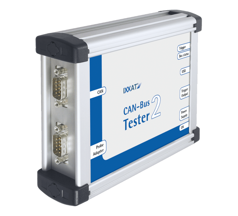
CAN-Bus-Tester 2
Powerful tool for analysis of physical CAN bus systems
Features and benefits
- Support of CAN, CANopen, DeviceNet and SAE J1939 systems
- Analysis of the signal-to-noise ratio of all telegrams (level, flanks, faults)
- Integrated oscilloscope with data interpretation for telegram analysis
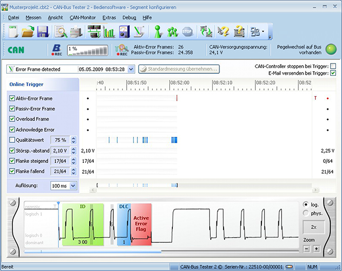
- Comprehensive trigger conditions for fault localization (logical and physical errors)
- Monitoring of bus status, bus load, error telegrams
- Wiring test (termination resistance, short circuits, interruptions, loop resistance, line length)
- Automatic baud rate detection
- Simple connection to CAN systems thanks to automatic baud rate detection and BusScan
- Simple operation via Windows program
- Simple generation of test protocols
- CAN monitor for transmission and reception of CAN messages (optional)
CAN-Bus-Tester
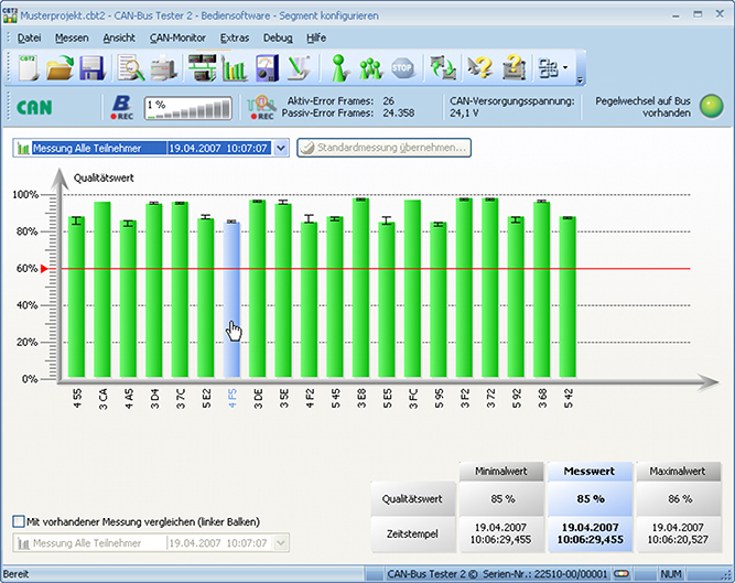
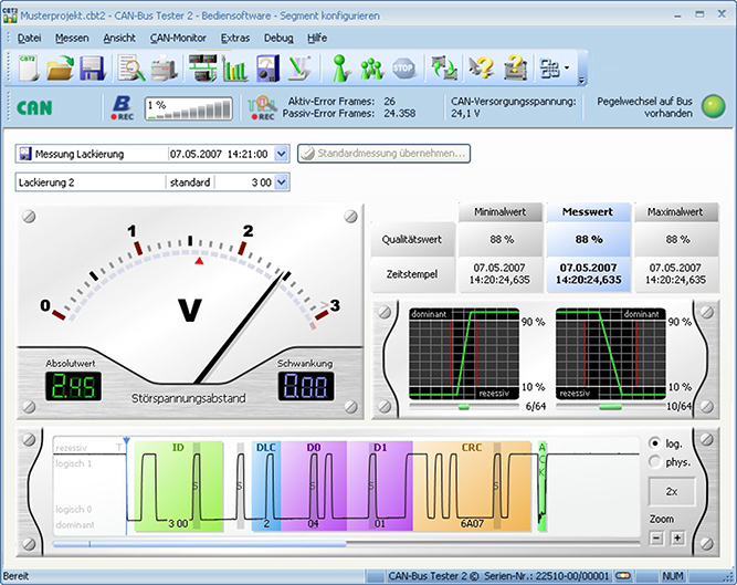
Typical faults during the operation of CAN bus systems, such as node failure, communication errors or complete system failure, are often caused by problems in the bus physics. Generally, devices which transmit messages with a low signal-to-noise ratio are highly susceptible to failures. The CAN-Bus-Tester provides an overview of the signal-to-noise ratios on the bus, enabling frequent causes of failures to be quickly identified and rectified. In addition, the most important logical analysis functions are also integrated into the Tester (otherwise found only in protocol analyzers). The Tester can be used for all bus systems with 11 or 29 bit identifiers according to 11898-2 and supports the CAN, CANopen and SAE J1939 protocols.
Automatic baud rate detection and the self-connecting BusScan allow the CAN-Bus-Tester to be quickly and easily connected to the system to be analyzed and started. The measurement results are automatically assigned to the relevant CAN identifiers or network nodes.
Depending on the test strategy, various methods of identifying faults can be used, such as a fast overview of the complete system, monitoring of an individual node or setting various trigger events (physical and/or logical faults and error-frames). When the trigger function is used, all faults are defined up to the individual bit position, are provided with a time stamp and displayed in the integrated oscilloscope. A trigger signal available via the external trigger output can be used to trigger an oscilloscope. A certain CAN message or an error telegram can thus be displayed selectively on the oscilloscope.
Rental service
The CAN-Bus-Tester is rented including support and problem analysis remotely by Twincomm. The minimum rental time is 2 weeks, but it can be extended on a weekly basis.
| Technical data | |
| Use | CAN according to ISO 11898-2 (High-Speed) with 11-bit or 29-bit identifier (CAN 2.0A and 2.0B) |
| Baudrate | 5 k, 10 k, 20 k, 33.3 k, 50 k, 62.5 k, 75 k, 83.3 k, 100 k, 125 k, 200 k, 250 k, 500 k, 800 k, 1000 kBit/s |
| Baudrate detection | All supported baudrates |
| Bit scanning | 64x, 10240 scanning points |
| Trigger output | BNC-socket, electrically isolated |
| Connection to CAN bus | Passive, 2 x 9-pole SUB-D connector |
| PC connection | Via USB, electrically isolated |
| Supply voltage | 9 ... 36 V DC, DIN 45323 low-voltage socket; |
| 0.15 ... 0.55A | |
| Dimensions and wight | 40 x 134 x 170 mm (H/W/L), approx. 600 g |
| With case: 504 x 354 x 119 mm, approx. 5000 g | |
| Safety/protection | EN 60950: 2003-03 / IP 20 according to EN 60529 |
| EMC | EN 61000-3-2: 2000, +A1: 2000, +A2: 2004 |
| EN 55022: 1998, +A1: 2000, +A2: 2003 | |
| EN 61000-6-2: 2001 | |
| Temperatur range | Operation: +5 °C ... +40 °C |
| Storage: -20 °C ... +60 °C | |
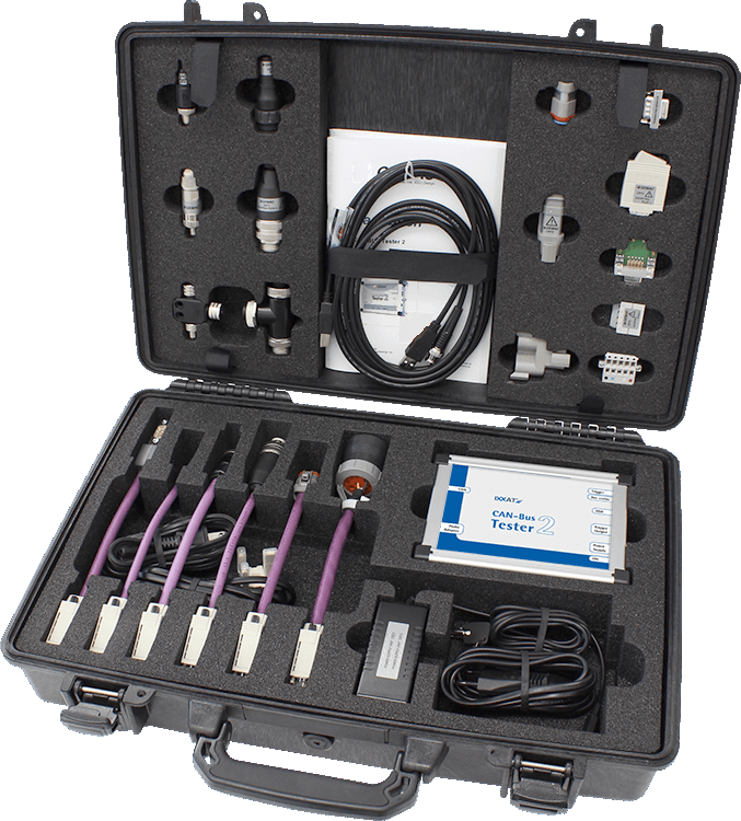
| Contents of delivery |
| - Basic device CAN-Bus-Tester CBT 2 |
| - CAN bus accessories 6 adapter cables: SUB-D, Open style, M12, 7/8”, SAE J1939-11, SAE-J1939-13 Shorting plug: SUB-D, Open style, M12, 7/8”, SAE J1939-11 Termination resistor: SUB-D, M12, 7/8”, SAE J1939-11 T- or Y-adapter: M12, 7/8”, SAE J1939-11 Adapter PCB for simple connection of an oscilloscope |
| - Power unit 100 V - 240 V / 50-60 Hz; 24 V, 500 mA; power cable (EU, UK, USA/Japan) |
| - BNC cable |
| - USB cable |
| - User's manual incl. CD with USB driver and application software |
| - Robust. lockable case |
Part number(s)
rental per week (minimal 2 weeks)