")
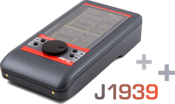
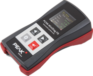
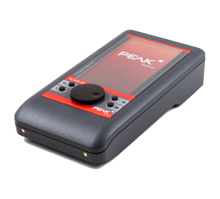
PCAN-Diag FD
Mobile Diagnostic Device for CAN and CAN FD
Features and Benefits
- Analysis of CAN and CAN FD networks at physical and protocol level
- Manual or automatic bit rate detection
- Switchable listen-only mode
- Symbolic display of incoming CAN messages using symbol files
- Create and maintain symbol files with the PCAN Symbol Editor
- Record incoming CAN messages on the internal memory card
- Playback of trace files
- Conversion of trace data to various output formats
- Transmission of individual CAN frames or CAN frame sequences
- Decimal, hexadecimal or binary input of CAN data.
- Transmission of CAN messages with readable ID and data by supporting symbol files
- Display of CAN bus load, error frames and much more
- Oscilloscope with two independent 100 MHz measurement channels
- Display of the CAN-High and CAN-Low signals and the difference
- Extensive trigger configuration
- Decoding of CAN and CAN FD frames
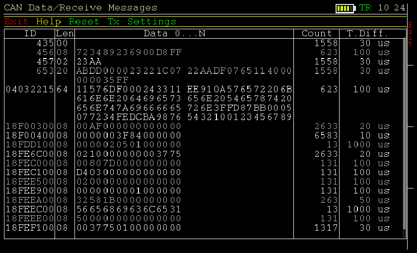
At the protocol layer, the incoming CAN traffic is displayed in a list, optionally with symbolic representation for better interpretability. For future analysis, a tracer is implemented that records the CAN traffic. In the outgoing direction, individual CAN messages or even complete CAN message sequences can be sent on the connected CAN bus, for example to query diagnostic data. Recorded CAN traces can also be played back. All functions at the protocol layer are available for CAN 2.0 and CAN FD.
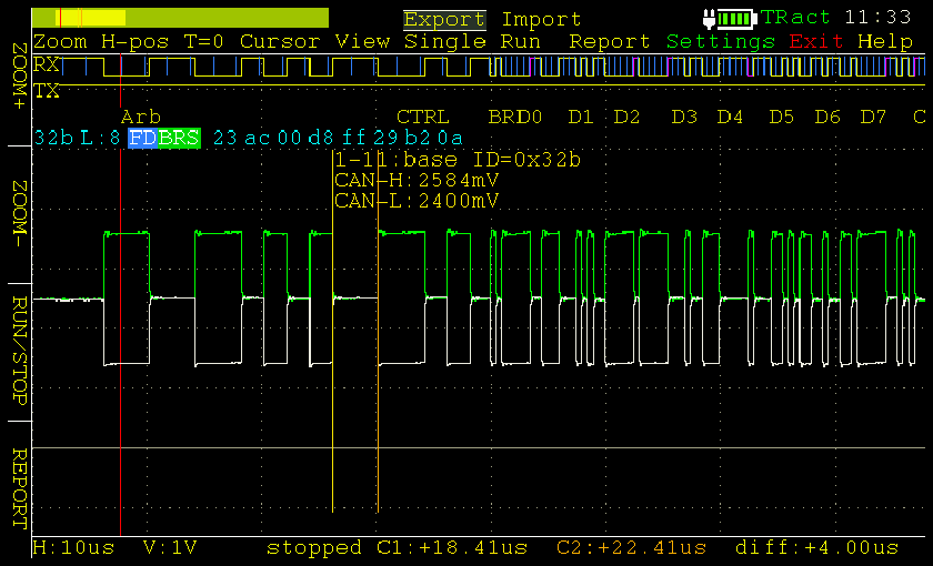
The oscilloscope function is used for a qualitative evaluation of the signal course on the CAN bus. Two independent measurement channels sample both lines CAN-High and CAN-Low with up to 100 MHz. Based on the signal course, the PCAN-Diag FD decodes CAN frames and displays their elements in the scope graphs.
The CAN FD standard (CAN with Flexible Data rate) is primarily characterized by a higher bandwidth for data transmission. A maximum of 64 data bytes per CAN FD frame (instead of 8 previously) can be transmitted at bit rates of up to 12 Mbit/s. CAN FD is backward compatible with the CAN 2.0 A/B standard, so CAN FD nodes can be used in existing CAN networks. In this case, however, the CAN FD extensions do not apply.
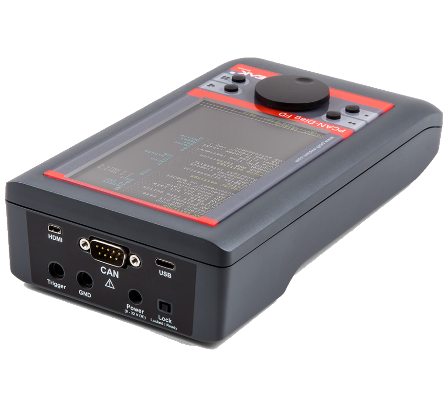
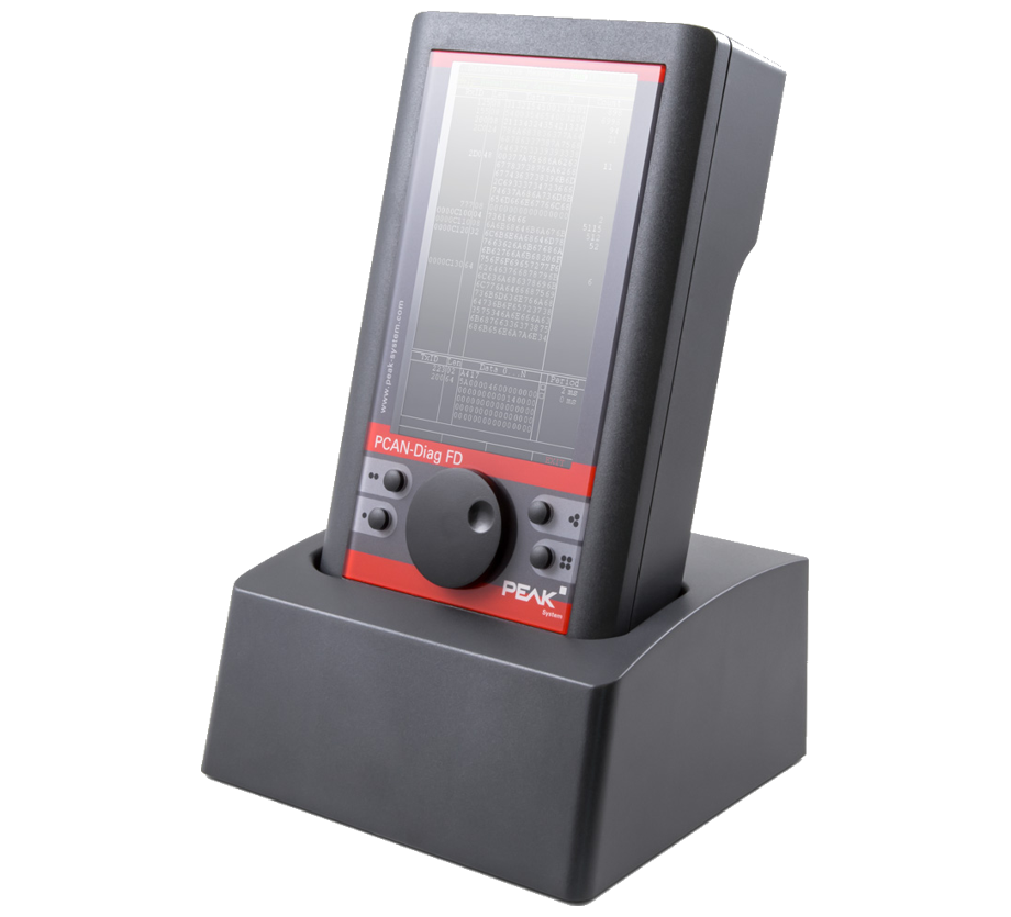
The PCAN-Diag FD is operated simply by a push button and four function keys. The device is powered externally or by the internal batteries that are automatically charged when externally powered. The charging process can be accelerated with the optional charging station.
| Technical data | |
| CAN | |
| CAN controller | CAN 2.0A/B |
| CAN baudrates | 10 kBit/s ... 1 Mbit/s |
| CAN-FD | |
| CAN-FD controller | ISO and Non-ISO standards |
| CAN-FD baudrates | CAN FD bit rates for the data field (64 bytes max.) 20 kbit/s ... 12 Mbit/s |
| CAN-FD transceiver | Microchip MCP2558FD |
| CAN connections | Dsub-9 Acc. to CiA 303-1 |
| Display | Color 800 x 480 pixels |
| Power supply | 9 ~ 28 Volt DC |
| Rechargable batteries | 6 x AA NiMH 1.2 V 1900 mAh |
| Temperature range | 0 ºC t/m +50 ºC |
| Certification | CE |
| Dimensions | 110 x 47 x 206 mm |
| Contents of delivery |
| - PCAN-Diag |
| - Configuration software PCAN-Diag FD Editor for Windows |
| - PCAN-Symbol Editor for Windows |
| - Conversion software PEAK-Converter for Windows |
| - USB cable |
| - Power supply (EU, UK, US) |
| - Micro HDMI to DVI cable |
| - Manual |
| - Quick start guide |